
 Caleb Turner
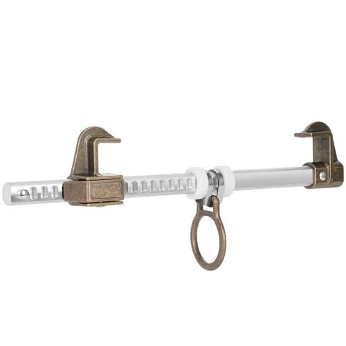
I recommend beginning the installation of the key support structure by carefully determining its position and dimensions. Accurate measurements are crucial to ensure stability and alignment with existing architecture. Create a detailed plan that considers load distribution and incorporates appropriate reinforcements.
Before proceeding, assess the existing framework for potential weaknesses. Identify load-bearing walls and any other structural elements that may influence the placement of your support component. This analysis will guide you in selecting the appropriate size and type of material necessary to meet safety standards.
Utilize temporary supports to hold the framework in place while the adjustments are made. This approach allows for precise alignment and ensures that the new structure will function correctly within the confines of the space. Secure all connections firmly, using high-quality fasteners and techniques that accommodate the specific characteristics of your building.
Finally, conduct a thorough inspection after installation to confirm that everything is stable and secure. This step is vital to ensure durability and safety in the newly configured area. Regular maintenance checks will further enhance the longevity of your newly installed support system, providing peace of mind for years to come.
Assessing Load Requirements for Steel Beam Installation
Begin by identifying the total load that the structure will support. This includes the dead load, which consists of the weight of the materials and permanent fixtures, and the live load, caused by occupancy and furniture. For residential spaces, the typical live load is 40 pounds per square foot, while the dead load should be calculated based on materials used in the ceiling and roof.

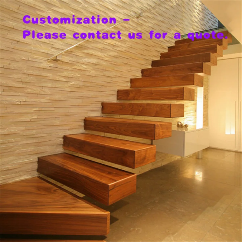

Next, determine the span of the support structure. Measure the distance from one support point to another, as this will significantly influence the sizing of the member. Longer spans generally require larger and heavier components to hold the load safely.
Utilize structural engineering software or consult engineering tables to match the calculated loads with the appropriate dimensions and weight specifications of the chosen supports. These tools provide insights into bending moments and shear forces that the structure will experience.
Engage with a qualified structural engineer to verify calculations. They can provide essential insights on local building codes, which dictate specific loads and safety factors that must be taken into account. Understanding these regulations ensures compliance and the longevity of your installation.
Finally, include a safety margin in your calculations. It’s advisable to design for loads exceeding the calculated requirements to accommodate unexpected pressures, such as snow accumulation or additional storage. This proactive measure enhances safety and stability.
Choosing the right steel beam type for your loft
Select a structural form based on spans and load requirements. I often recommend I-beams for their strength and efficiency in weight distribution. Their design allows for maximum load capacity while minimizing weight, which is crucial in upper spaces.
Consider using wide flange beams if aesthetic appeal is essential. These offer a smooth finish and can be left exposed, enhancing the design of the space. For smaller openings, a channel beam could suffice, providing adequate support while taking up less vertical height.
Assessing material properties is key. For durability, opt for S235 or S275 grade steel. They offer the balance between strength and cost, perfect for residential projects. Corrosion resistance can be improved with appropriate coatings, especially in environments prone to moisture.
Pre-fabricated beams can expedite the installation process; they are manufactured to specification and delivered ready to install. This cuts down on labor time and ensures accuracy in measurements.
Lastly, always consult with a structural engineer to verify your choice against local building codes and ensure the selected configuration aligns with safety regulations. Their expertise is invaluable in making the best decision for your renovation project.
Measuring and Marking the Installation Points
Measure the total span where the support structure will be placed. Use a measuring tape to determine the distance from one end of the space to the other, ensuring accuracy to within an eighth of an inch. For pinpoint precision, mark these measurements on the floor with a chalk line or marker.
Identify the load-bearing walls adjacent to the intended support. Typically, these points will serve as the main supports. Use a level to ensure that your markings are aligned horizontally; this helps maintain the integrity of the construction.
Next, calculate the center point where the load will be concentrated. Divide the total span measurement by two, and mark this point clearly on the ceiling or floor. This location is critical for balancing the weight and ensuring even distribution during installation.
To enhance accuracy, create a grid system on your markings. Draw perpendicular lines to intersect at your previously determined points. This will provide clarity and assist in aligning the structural component correctly during the installation phase.
Finally, verify all measurements and markings before proceeding. Double-checking at this stage can prevent costly errors later on. Once satisfied with the measurements, secure your workspace and prepare for the subsequent steps in the construction process.
Removing Existing Structures Safely Before Installation
Begin the removal process by ensuring all utilities, such as electricity and plumbing, are properly disconnected. It’s essential to identify any structural elements that will be affected during the extraction process.
Utilize a reciprocating saw for cutting through framing members and a pry bar for lifting and removing materials. Ensure adequate support is given to any surrounding structures to prevent unintentional collapse.
In my experience, wearing appropriate protective gear is non-negotiable–this includes hard hats, safety goggles, gloves, and steel-toed boots. Additionally, inform all individuals involved about the sequence of activities planned, and establish clear communication protocols.
To ensure a safe workspace, create a designated removal area, keeping it free from debris and hazards. Consider the following table for an organized approach to the removal process:
| Step | Description | Safety Precautions |
|---|---|---|
| 1 | Disconnect utilities | Check for live connections |
| 2 | Identify support structures | Mark critical points |
| 3 | Remove fixtures | Handle with care |
| 4 | Cut framing elements | Use saw with caution |
| 5 | Clear and clean workspace | Avoid slips and trips |
Once the area is cleared, inspect the remaining structure for stability before proceeding. It’s advisable to consult a structural engineer to verify that all necessary loads have been adequately addressed prior to beginning new installations.
Preparing the Loft Space for Beam Placement
Clear the area thoroughly. Move any furniture, tools, or storage items from the installation zone. This allows for unobstructed access during the process.
Inspect the ceiling structure. Check for any signs of damage or decay in the existing timbers. Reinforce or replace any compromised sections to ensure a stable foundation for the new support.
Next, assess the surrounding walls. Ensure they are straight and level. If needed, make adjustments to avoid complications when securing the new support.
Consider any utilities in the vicinity. Identify electrical wires, plumbing pipes, and HVAC ducts. Relocate or shield them to avoid damage during the installation.
Creating a Safe Workspace
Set up proper lighting to illuminate the work area. Utilize portable work lights if necessary. A well-lit environment reduces the risk of accidents.
Establish a secure area around the workspace. Use barriers to keep children and pets away. Safety should be a top priority during this project.
Gathering Necessary Tools and Materials
Prepare all tools needed for the task. Common items include a measuring tape, level, saw, drill, and safety gear like gloves and goggles. Having everything at hand minimizes disruptions during the installation.
Finally, review and double-check your plans. Ensure that every detail aligns with the project’s goals. A thorough final review helps to avoid potential delays or issues during the process.
Using Temporary Supports During Installation
Temporary supports are vital for maintaining stability while placing the structural element. Ensure to use adjustable props or strong timber bracing for this task.
Follow these steps to set up your supports:
- Position supports directly under the existing framing where the new element will be placed.
- Adjust the height of the props to provide firm contact with the framing. Ensure they are plumb and securely positioned.
- Employ cross-bracing between supports for added stiffness, particularly in wider spaces.
Make it a priority to check the alignment of your framework and ensure that it remains balanced under load. Misalignment can lead to structural issues down the line.
Before removing the supports:
- Verify that the new structure is secure and well fastened.
- Gradually release the tension on supports to avoid sudden shifts.
- Remove supports carefully, observing any movement in the new installation.
By applying these techniques, I can ensure the integrity of the installation during this critical phase of the project.
Securing the Steel Beam to Existing Structures
Begin by identifying the locations where your support structure meets the existing framework. Ensure these junctions can bear the additional weight and loads applied by the new support. Use a laser level to verify that all contact points align horizontally and vertically.
Fixing Methods
Utilize robust bolts or heavy-duty shear plates at each connection point. Pre-drill holes in the existing structures for precision, preventing any cracking or damage to surrounding materials. Secure with lock washers or nuts to withstand shear forces over time.
Ensuring Stability
After attaching, double-check all connections for tightness. Employ a torque wrench to meet specified values, ensuring no movement occurs under load. Assess the structural integrity periodically, especially during the initial stages of usage, to confirm the reinforcement holds strong.
Ensuring Proper Beam Alignment and Leveling
Initiate alignment by utilizing a laser level to project a reference line along the intended placement. This enables accurate positioning. Ensure that each end of the support is checked for level; make adjustments if necessary.
Begin by measuring the distance from the floor to the reference line. Mark these points on both sides to create a visual alignment guide.
To maintain a precise horizontal plane, use shim packs. Place them beneath the supports to raise or lower the structure until it aligns with the reference line.
The following steps will help ensure proper alignment:
- Install temporary bracing across multiple locations to stabilize the placement during adjustments.
- Utilize a bubble level across various sections to verify that each part remains evenly distributed.
- Revisit the laser level throughout the process to confirm that adjustments haven’t shifted during installation.
Once positioned, double-check measured points before final attachment. If any discrepancies arise, adjust the shims or bracing accordingly. Securely fasten to existing structures once satisfied with alignment.
Conclude by inspecting the alignment after securing to ensure stability. This verification reinforces the integrity of the entire installation.
Finishing touches and inspections post-installation
Conduct a thorough inspection of the installed support structure, including connections and fasteners. Check all joints for secure attachment, ensuring they comply with local building codes.
Apply a protective coating or paint to prevent rust and corrosion, especially if the material will be exposed to moisture. Choose a durable finish suitable for structural applications.
Evaluate load distribution across the entire framework. Use a level to confirm proper alignment and adjust as needed before finalizing any finishing work.
| Inspection Area | Checklist Items | Notes |
|---|---|---|
| Connections | Ensure all bolts and welds are tight | No visible gaps |
| Alignment | Confirm horizontal and vertical level | Adjust if necessary |
| Protective Coating | Apply one layer minimum | Consider weather exposure |
Document all inspection findings, including photographs of approved connections. This record can serve as proof for future renovations or assessments.
Engage a structural engineer for a formal assessment if any discrepancies arise. Their expertise can offer peace of mind and ensure long-term safety.